Remote Shutdown Wiring
2022-01-06 16:37
The interface and connection wiring of remote shutdown functions are different for different series. This article focus on 2 different types.
Interface with Plate
The GW DNS, MS and MT series need to remove the plate to connect the RS485 cables for remote shutdown functions.
The diagrams below shows the interface components for RS485&DRED of MS series.

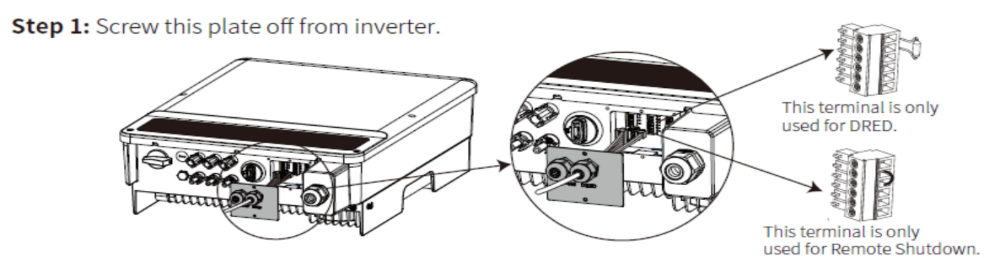
The pins for remote shutdown are also different for DNS, MS and MT series. (Photo Annex)
The connection steps of remote shutdown of the MS series are follows:
Step 1: Screw this plate with the word “DRED” off from inverter and pull out the 6 pin terminal with remote shutdown function.
Step 2: remove the short-circuited wire from the connection with a screwdriver.
Step3: Use a double core wire that is compatible with the diameter of the waterproof head, and put it through the section marked with the word “DRED”.
Step 4: Plug the wire into the terminal and lock it with a screwdriver. The wire grommets should be placed the same as the shorting wires, as per the figure below, where it is illustrated how the second and third grommets get wired from left to right.
Communication terminal (XS, SDT G2, SMT, HT)
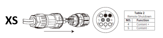
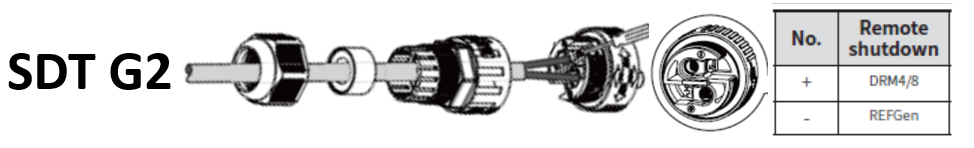
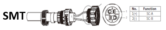
Most of GW inverters (like XS, SDT G2, SMT and HT) use the new connector with multiple ports. The users don’t need to remove the plate. They only need to take the communication terminal from the accessory pack and connect the cables to the corresponding port and then connect the terminal to the right communication interface onto the inverter.
The figure below shows the Remote Shutdown terminals for XS, SDT G2, SMT and HT series. The user manual provides the details about which port should be connected to the cables.
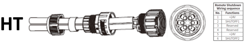
The connection steps of remote shutdown of the HT series are follows:
Step 1: remove the waterproof covers from inverter and take the communication terminal from the accessory pack and disassemble it as shown in the diagram.
Step 2: dismantle the resistor or short-circuit cable.
Step 3: choose RS485 shielded twisted pair wire an strip it as shown in the diagram below, then connect the terminal and crimp it tightly.
Step 4: put the cable through the connector and connect to the corresponding port according to the wiring sequence (the diagram below shows the sequence for HT 1100V). Then assemble the terminals and tighten them.
Step 5: connect the terminal to the right position onto the inverter.
Remote Shutdown for multiple inverters
When multiple inverters need to realize remote shutdown function, the inverters should be connected hand in hand and the maximum number of inverters is 20.
The communication interface and port for remote shutdown of different series are also different. Please refer to GW user manuals.

Installers Friendly(Part I)

Installers Friendly(Part II)

Dear User,
Thank you for visiting our community. We would love to hear about your opinion - simply fill out and hit confirm. Thank you for your feedback!

Insert your details below to receive information


